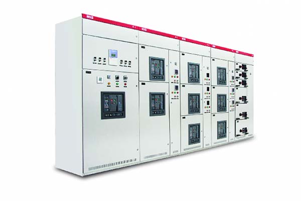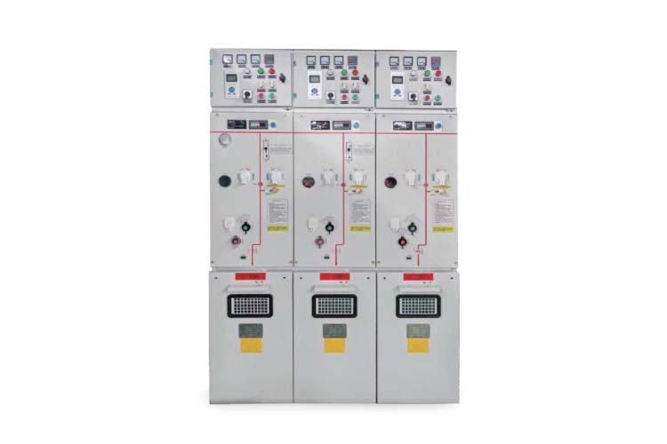
KYN61-40.5 Armored Removable Metal- Enclosed switchgear
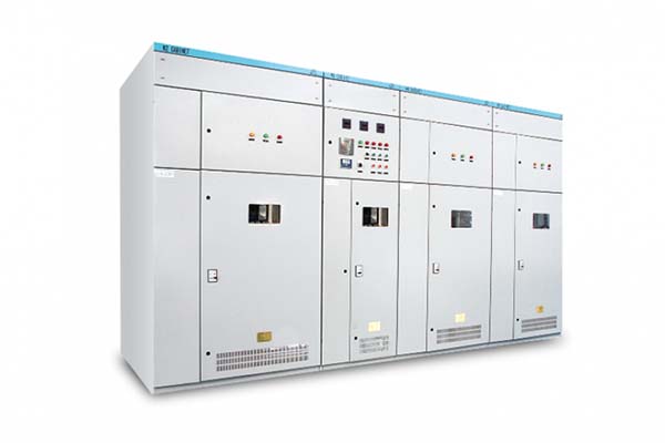
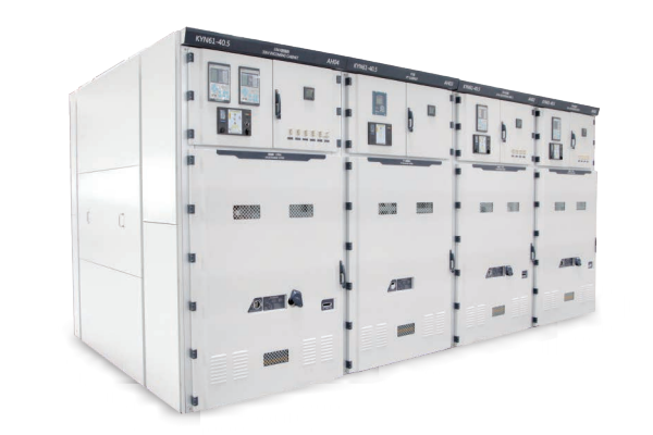
The KYN61-40.5 type magnetically-actuated withdrawable AC metal-enclosed switchgear is characterized primarily by its internal configuration, which features the fully insulated ZN85-40.5 vacuum circuit breaker and a spring operating mechanism. The cabinet body is constructed from powder-coated steel plates, a design that enhances the precision of the mechanical interlocking between the withdrawable unit (trolley) and the cabinet components. Consequently, the trolley can be inserted into or withdrawn from the cabinet with great ease, offering strong interchangeability. Furthermore, the switchgear boasts an aesthetically pleasing appearance, offers a comprehensive range of configuration schemes, and ensures safe and reliable operation.
Description
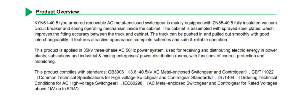
Product Overview
This product is designed for use in 35 kV, 3-phase AC, 50 Hz power systems. It serves as a distribution unit for receiving and distributing electrical energy within the distribution rooms of power plants, substations, and industrial and mining enterprises, incorporating functions for control, protection, and monitoring.
This product complies with the following standards: GB 3906 “AC Metal-Enclosed Switchgear and Controlgear for Rated Voltages Above 3.6 kV and Up to 40.5 kV,” GB/T 11022 “Common Specifications for High-Voltage Switchgear and Controlgear Standards,” DL/T 404 “Technical Specifications for Ordering AC High-Voltage Switchgear,” and IEC 60298 “AC Metal-Enclosed Switchgear and Controlgear for Rated Voltages Above 1 kV and Up to 52 kV.”
Technical Parameters
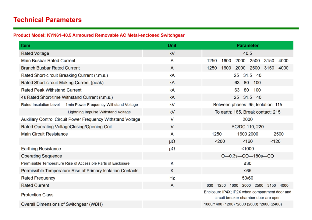
Product Model: KYN61-40.5 Armored Withdrawable AC Metal-Enclosed Switchgear
| project | unit | parameter |
| Rated Voltage | kV | 40.5 |
| Main Busbar Rated Current | A | 1250 1600 2000 2500 3150 4000 |
| Branch Busbar Rated Current | A | 1250 1600 2000 2500 3150 4000 |
| Rated Short-Circuit Breaking Current (RMS) | kA | 25 31.5 40 |
| Rated Short-Circuit Making Current (Peak) | kA | 63 80 100 |
| Rated Peak Withstand Current | kA | 63 80 100 |
| 4s Rated Short-Time Withstand Current (RMS) | kA | 25 31.5 40 |
| Rated Insulation Level: 1-Minute Power-Frequency Withstand Voltage | kV | alternate 95 separate 115 |
| Lightning Impulse Withstand Voltage | Relatively 185 Fracture Surface 215 |
| Power-Frequency Withstand Voltage of Auxiliary Control Circuits | V | 2000 |
| Rated Operating Voltage Opening and Closing Coil | V | AC/DC 110 、 220 |
| Main Circuit Resistance | A | 630 1250 1600 2000 2500 3150 4000 |
| μΩ | <200<160<120 | |
| Grounding Resistance | μΩ | ≤1000 |
| Operation Sequence | O—0.3s—CO—180s—CO | |
| The accessible parts of the enclosure are permitted to undergo a temperature rise. | K | ≤30 |
| Allowable Temperature Rise of a Single Isolating Contact | K | ≤65 |
| Rated Frequency | Hz | 50/60 |
| Rated Current | A | 630 1250 1600 2000 2500 3150 4000 |
| Protection Class | Enclosure rating: IP4X; IP2X when the compartment door or circuit breaker compartment door is open. | |
| Switchgear Dimensions (Width × Depth × Height) | 1680/1400 (1200) *2800 (2600) *2600 (2400) |
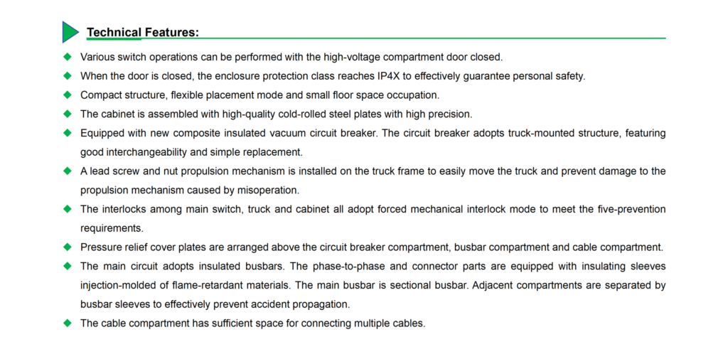
Technical Features
· Enables various switching operations to be performed while the high-voltage compartment door remains closed.
· Achieves an enclosure protection rating of IP4X when the door is closed, effectively ensuring personnel safety.
· Features a compact structure and flexible layout options, thereby minimizing floor space requirements.
· The cabinet body is assembled from high-quality cold-rolled steel plates, ensuring high structural precision.
· Equipped with a new-generation composite-insulated vacuum circuit breaker; the breaker utilizes a floor-standing withdrawable trolley structure, characterized by excellent interchangeability and ease of replacement.
· The trolley frame incorporates a lead screw and nut propulsion mechanism, allowing for effortless movement of the trolley while preventing damage to the mechanism caused by accidental mishandling.
· Interlocks between the main switch, the trolley, and the cabinet body utilize a mandatory mechanical interlocking system, fully satisfying the “Five Preventions” safety requirements.
· Pressure relief covers are installed above the circuit breaker compartment, the busbar compartment, and the cable compartment.
· The main circuit utilizes insulated busbars; phase-to-phase connections and joints are fitted with insulating sleeves injection-molded from flame-retardant materials. The main busbar is segmented, with adjacent cabinet sections separated by busbar bushings to effectively prevent the propagation of faults.
· The cable compartment offers ample space, allowing for the connection of multiple cables.