Modular Low-Voltage Switchgear
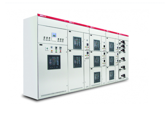
This low-voltage switchgear is an advanced complete set of low-voltage switching equipment. The cabinet features a highly flexible framework structure that requires no further adjustment once assembly is complete. The interior can accommodate various standard components to meet diverse application requirements. Because the electrical configuration of the entire system adopts a modular and combinable design, this optimized structural approach not only fulfills the requirements of various components but also adapts to different operating environments while achieving the corresponding protection degrees (IP ratings).
Description
Technical Features & Performance
1. Highly Modular and Flexible Configuration
Functional units feature a standardized modular design with a compact structure, allowing for the flexible combination of drawer units with varying module sizes to achieve greater functional integration within limited space. All drawer units are fully interchangeable, enabling rapid replacement and significantly reducing maintenance and repair times.
2. Fully Isolated Safety Design
Internally, the cabinet is strictly partitioned according to primary and secondary circuit functions into distinct compartments: device drawers, cables, busbars, and secondary terminals. These compartments are completely separated from one another using grounded steel plates and flame-retardant insulating barriers; with no exposed live parts, the design fundamentally ensures both the operational safety of the equipment and the personal safety of on-site personnel.
3. Triple-Position Mechanical Interlock Protection
All drawer units are equipped with reliable mechanical interlock mechanisms capable of precisely locking the unit in the “Work,” “Test,” and “Disconnected” positions. This effectively prevents electrical accidents caused by operational errors, thereby enhancing the overall safety and stability of the system.
4. Flexible Installation and Layout Options
The system supports two types of functional units: drawer-type and fixed-compartment-type. The main busbars can be flexibly positioned at the rear or the top of the cabinet, depending on on-site power entry and exit requirements. Cabinets can be installed side-by-side or back-to-back; for non-back-to-back installations, the design supports double-sided door access, greatly facilitating routine maintenance and inspection of the equipment.
5. Diverse Power Entry and Exit Schemes
A variety of power entry and exit methods are available—including top-in/top-out, top-in/bottom-out, bottom-in/bottom-out, and bottom-in/top-out—allowing users to select the optimal configuration based on on-site civil engineering conditions and wiring requirements, thereby reducing construction complexity and modification costs.
6. Standardized Drawer Unit System
Based on the 8E (200 × 600 mm) unit as the fundamental functional module, a comprehensive range of specifications is available for selection, including 8E/4, 8E/2, 8E, 12E, 16E, 20E, 24E, and 36E. A single cabinet can support a maximum configuration capacity of up to 72E, effectively meeting power distribution requirements across various capacity levels.
7. Excellent Environmental Adaptability
The standard enclosure offers an ingress protection (IP) rating of no less than IP40 and features an efficient structural design that facilitates natural ventilation and heat dissipation. Designed for harsh industrial environments—such as those involving dust and moisture—the unit can be custom-upgraded to an IP54 protection rating, ensuring long-term, stable operation under complex working conditions.
Technical Specifications
Product Model: Modular Low-Voltage Switchgear
| Item | Unit | Parameter |
| Rated Operating Voltage | V | 380 (400) |
| Rated Insulation Voltage | V | 660 (1000) |
| Rated Voltage of Auxiliary Circuit | V | 220/380 (400) |
| Rated Voltage of Auxiliary Circuit | V | AC/DC 110, 220 |
| Rated Frequency | Hz | 50 (60) |
| 1min Power Frequency Withstand Voltage of Main Circuit | kV | 2.5 |
| Peak Withstand Voltage of Main Circuit | kV | 8 |
| Rated Current of Main Busbar | A | ≤5000 |
| Rated Current of Distribution Busbar | A | 800~2000 |
| Rated Short-Time Withstand Current of Main Busbar | kA/1s | 35~100 |
| Rated Peak Withstand Current of Main Busbar | kA | 105~220 |
| Rated Short-Time Withstand Current of Distribution Busbar | kA/1s | 35~80 |
| Rated Peak Withstand Current of Distribution Busbar | kA | 105~176 |
| Busbar System – Three-Phase Four-Wire | – | A, B, C, PEN |
| Busbar System – Three-Phase Five-Wire | – | A, B, C, N, PE |
| Executive Standard | – | IEC60439-1, GB7251.1 |
Product Gallery